Introduction
Imagine this: Your entire automated production line comes to a grinding halt. The culprit? Not the expensive PLC or the massive robotic arm, but a small, unassuming component—the pneumatic solenoid valve.
Often called the “muscle” of automation, pneumatic solenoid valves are the critical link between your electronic control system and your pneumatic power. They determine when cylinders extend, when grippers open, and when air blasts clean a part. Selecting the wrong valve (or installing it incorrectly) can lead to frustrating air leaks, sluggish machine performance, and costly downtime.
Whether you are a design engineer selecting components for a new machine, or a maintenance technician trying to fix a valve that’s “stuck open,” this guide is for you. We’ll cut through the jargon and cover everything from working principles and ISO symbols to a practical troubleshooting checklist that could save you hours of diagnostic time.
What is a Pneumatic Solenoid Valve?
At its core, a pneumatic solenoid valve is an electromechanical device used to control the flow of compressed air. It acts as a switch: it takes an electrical signal (from a PLC, timer, or button) and converts it into a pneumatic action.
How it works (The Simple Version): Think of it like a light switch, but for air.
- Electrical Input: You send an electrical signal (usually 24V DC or 220V AC) to the Solenoid Coil.
- Magnetic Action: The coil creates a magnetic field that moves a small internal part called the Armature (or Plunger).
- Pneumatic Output: This movement opens or closes an orifice inside the valve body, allowing compressed air to flow through to your cylinder or actuator.
Technically, these are also known as Directional Control Valves because their primary job is to direct airflow to different ports (e.g., to extend or retract a cylinder).
Working Principle: Direct Acting vs. Pilot Operated
When selecting a pneumatic solenoid valve, you’ll encounter two main types based on how they move the internal spool. Choosing the wrong one is the #1 reason for valve failure in low-pressure applications.
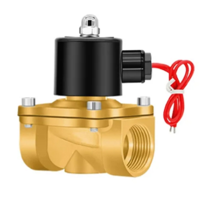
1. Direct Acting Solenoid Valves (直动式)
Think of this as “brute force.”
- How it works: When the coil is energized, the magnetic force directly pulls the armature (plunger) to open the orifice. The coil does all the heavy lifting.
- Pros:
- Zero Differential Pressure: It works even with 0 PSI (vacuum or very low pressure).
- Fast Response: Immediate action.
- Cons:
- High Power Consumption: Requires a larger coil to generate enough force.
- Limited Flow/Pressure: Hard to open large valves against high pressure.
- Best For: Small orifices, low flow rates, vacuum applications, or simple on/off tasks.
2. Pilot Operated Solenoid Valves (先导式)
Think of this as “smart leverage.”
- How it works: The solenoid coil only opens a tiny “pilot” hole. The compressed air itself then rushes through this pilot hole to push the main spool. It uses the system’s own air pressure to do the heavy lifting.
- Pros:
- Low Power Consumption: A tiny coil can control a huge valve.
- High Flow Rates: Can handle large volumes of air easily.
- Cons:
- Minimum Operating Pressure Required: It needs input pressure (usually > 0.15 MPa or ~22 PSI) to work. If your air supply is weak, the valve won’t shift.
- Slower Response: Slightly slower than direct acting (milliseconds difference).
- Best For: Most general industrial automation, operating large cylinders, high flow applications.
Pro Tip: Never use a standard Pilot Operated valve for a vacuum system unless it has an external pilot supply. The vacuum won’t provide the pressure needed to shift the spool!
Classification: Understanding “Ways” and “Positions”
You’ll often see valves described as 2/2, 3/2, or 5/2. This isn’t a fraction; it’s a code that tells you exactly what the valve can do.
- The First Number (Ways/Ports): How many holes (ports) are in the valve body for air to enter or exit? (e.g., Inlet, Outlet, Exhaust).
- The Second Number (Positions): How many switching states does the valve have? (e.g., Open/Closed, Extend/Retract).
Let’s break down the most common types and—crucially—which cylinder they control.
1. 2/2 Way Solenoid Valve (2 Ports, 2 Positions)
- The Function: The simplest type. It has one inlet (P) and one outlet (A). It’s either ON (air flows) or OFF (air stops).
- Best Application: Air blow guns, simple shut-off valves, or filling a tank.
- Circuit Logic: It acts like a standard water faucet.
2. 3/2 Way Solenoid Valve (3 Ports, 2 Positions)
- The Function: Designed for Single Acting Cylinders (cylinders with a spring return).
- Port 1 (P): Air Supply Inlet.
- Port 2 (A): Outlet to Cylinder.
- Port 3 (R/Ex): Exhaust (Releases air when the valve closes).
- Best Application: Operating spring-return cylinders, grippers, or acting as a pilot signal for larger valves.
- NC vs. NO:
- Normally Closed (NC): Air is blocked when the valve is off. (Cylinder stays retracted).
- Normally Open (NO): Air flows when the valve is off. (Cylinder stays extended).
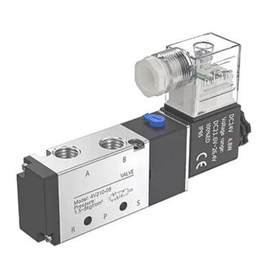
3. 5/2 Way Solenoid Valve (5 Ports, 2 Positions) – The Industry Standard
- The Function: The workhorse of automation. It is designed specifically for Double Acting Cylinders (cylinders that need air to extend AND air to retract).
- It has 1 Inlet, 2 Outlets (A & B), and 2 Exhausts (R1 & R2).
- How it Works:
- Position 1: Air flows to Outlet A (Cylinder extends), while Outlet B exhausts.
- Position 2: Air flows to Outlet B (Cylinder retracts), while Outlet A exhausts.
- Best Application: Packaging machines, assembly lines, and any task requiring controlled push/pull motion.
4. 5/3 Way Solenoid Valve (5 Ports, 3 Positions)
- The Function: Similar to a 5/2 valve, but it has a third “center” position. When the coil is not energized, springs push the spool to the middle state.
- Why use it? If you need to stop a cylinder mid-stroke (safety stop) or let it “float” freely.
- Center Types:
- Closed Center: All ports blocked. The cylinder freezes in place.
- Exhaust Center: Both sides of the cylinder exhaust. The piston can be moved by hand.
- Pressure Center: Both sides are pressurized. Used for specific balancing applications.
Key Specifications for Selection: How to Choose the Right Valve
Selecting a pneumatic solenoid valve isn’t just about matching the port size. You need to consider the electrical interface, flow capacity, and the environment it will operate in. Here is your checklist:
1. Voltage: DC 24V vs. AC 220V
- 24V DC (Standard): This is the safest and most common choice for modern automation. DC coils run cooler and are quieter.
- 110V / 220V AC: Still used in older machines, but beware: AC coils can produce a constant buzzing noise (hum) and tend to generate more heat.
- Pro Tip: If you are upgrading a machine, switch to 24V DC if possible. It extends the coil life significantly.
2. Flow Rate (Cv Factor) vs. Port Size
Don’t make the rookie mistake of buying a valve just because it has a 1/4″ port.
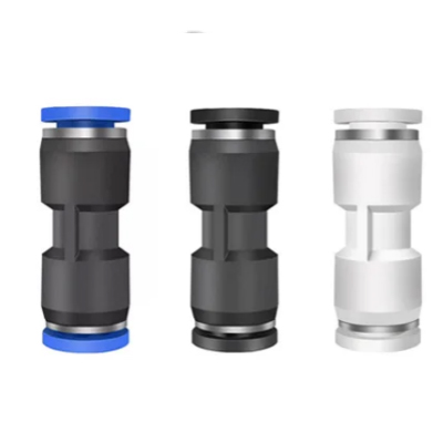
- Port Size (e.g., G1/4″, NPT 1/4″): Tells you what fitting fits.
- Cv Factor (Flow Coefficient): Tells you how much air actually gets through.
- A restrictive valve (Low Cv) will make your cylinder move slowly, no matter how high the pressure is.
- Rule of Thumb: Match the valve’s flow rate to the cylinder’s bore size. For a 40mm bore cylinder, a valve with Cv=0.8 (approx. 1/4″ port) is usually sufficient.
3. Wiring & Connectors (Don’t Forget the Plug!)
The valve body is useless without power. Most industrial valves use DIN 43650 Connectors.
- Form A (18mm): The big square one. Standard for larger valves.
- Form B (11mm / 10mm): The middle size. Note: Check if you need 11mm (Industrial Standard) or 10mm (DIN Standard) spacing.
- Form C (8mm / 9.4mm): The tiny one. Note: 8mm is most common, but 9.4mm exists.
- LED Indicators: Always buy connectors with LED lights. Why? When a machine stops, that tiny light tells you instantly if the valve is receiving power, saving you 20 minutes of testing with a multimeter.
4. Air Quality: To Lube or Not to Lube?
- The Old Way: Adding oil mist (lubricator) to the air.
- The Modern Way: Most new pneumatic solenoid valves are “Lubed for Life” (pre-greased at the factory).
- Warning: Once you start adding oil, you cannot stop. The oil mist washes away the factory grease. If the oiler runs dry, the valve seals will dry out and fail.
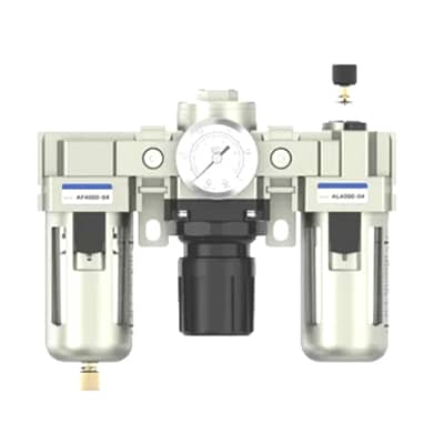
- Recommendation: Use clean, dry, filtered air (Standard 5-micron filter). Don’t add oil unless you are running extremely high-speed cycles (> 500 cycles/min).
Advanced Troubleshooting Guide: Fix It Like a Pro
So, your machine has stopped, and the solenoid valve is the prime suspect. Before you order a replacement, try these diagnostic steps. You might fix the problem in 5 minutes without spending a dime.
Scenario 1: Air is Leaking from the Exhaust Port (The #1 Myth)
- The Symptom: You hear a constant hiss of air coming from the valve’s Exhaust Port (R or S).
- The Knee-Jerk Reaction: “The valve seals are bad! I need a new valve.”
- The Likely Reality: It’s not the valve; it’s the cylinder.
- Inside the cylinder, the piston seal might be worn out. Air is bypassing the piston, traveling back up the return line, and escaping through the valve’s open exhaust port.
- The Test:
- Disconnect the air line going to the cylinder.
- If air stops leaking from the valve exhaust, the valve is fine.
- If air comes out of the cylinder port you just disconnected, your cylinder seals are blown.
Scenario 2: The Coil is Hot (Is it Burning?)
- The Symptom: You touch the black coil, and it feels hot.
- The Reality Check: Solenoid coils are designed to get warm. Operating temperatures of 60°C to 80°C (140°F – 175°F) are normal. If you can touch it for a second but not hold it, that’s usually fine.
- When to Worry:
- If the plastic is melting or smells like burning rubber.
- If the valve is buzzing loudly (AC coils only).
- Fix: Check if the voltage is correct (e.g., putting 24V into a 12V coil) or if dirt has jammed the armature, preventing it from closing fully (which causes AC coils to overheat).
Scenario 3: The Valve Clicks but Doesn’t Switch
- The Symptom: You hear the “click” of the solenoid, but the cylinder doesn’t move.
- The Diagnosis: The coil is working, but the air isn’t flowing.
- The Test (Manual Override):
- Look for a small button or screw (usually red or slotted) on the valve body near the coil. This is the Manual Override.
- Press or turn it.
- If the valve switches manually: The problem is electrical (weak voltage or bad signal).
- If the valve feels stuck manually: The spool is jammed with dirt or debris. You need to take it apart and clean it.
Quick Troubleshooting Logic
- No Click, No Action? → Check electrical signal (LED light on connector?).
- Click, No Action? → Check air pressure (Is it > 0.15 MPa for pilot valves?).
- Leak at Exhaust? → Check cylinder seals first.
Conclusion: Selecting the Right Valve for Long-Term Success
Pneumatic solenoid valves are deceptively simple components, but they carry the weight of your entire automation process. A misapplied valve—like using a Pilot Operated valve on a vacuum line, or an AC coil in a quiet lab—can lead to endless headaches and downtime.
To wrap up, here is your “Golden Rule Checklist” for selecting the perfect valve:
- Match the Function:
- Use 5/2 Way for Double Acting Cylinders.
- Use 3/2 Way for Single Acting Cylinders or Air Blow.
- Check the Pressure:
- Ensure you have at least 0.15 MPa (~22 PSI) for Pilot Operated valves.
- Go for Direct Acting if you need vacuum or zero-pressure startup.
- Choose the Voltage Wisely:
- Stick to 24V DC for safety, longevity, and quiet operation.
- Always use LED Indicators on your DIN connectors for easier troubleshooting.
- Keep the Air Clean:
- Modern valves are “Lubed for Life.” Stop adding oil mist! Just filter out the water.
Ready to Upgrade Your Pneumatic System?
Whether you are designing a new packaging machine or retrofitting an old production line, we have the high-flow, durable solenoid valves you need.
- Need help sizing your valve? Contact our engineering team for a free consultation.