Compressed air systems are the lifeblood of modern industrial manufacturing, but they hide a silent, potentially costly threat: backflow. When compressed air is forced to travel in the wrong direction, it doesn’t just cause a minor drop in system efficiency. It can lead to catastrophic, irreversible damage to your expensive air compressors and sensitive downstream pneumatic equipment.
This is exactly where pneumatic check valves come into play. Often overlooked due to their simple, compact design, these small components act as the ultimate, cost-effective insurance policy for your entire pneumatic circuit. By allowing compressed air to flow freely in one designated direction while strictly working to prevent reverse flow, a high-quality air line check valve ensures your system operates safely, predictably, and efficiently.
In this comprehensive guide, we will break down exactly how these essential valves work, explore their critical applications, and help you determine the best configuration to protect your machinery from the hidden dangers of backflow.
What is a Pneumatic Check Valve?
At its core, a pneumatic check valve—frequently referred to as a pneumatic non-return valve or a one-way air valve—is a fundamental directional control device used in compressed air systems. Its primary function is elegantly simple yet critically important: it allows compressed air to flow freely in one designated direction (forward flow) while completely blocking any airflow from returning in the opposite direction (reverse flow). Think of it as a strict, automated one-way street for your air lines.
Because they operate automatically based on the pressure differentials within the system, they require no external control or human intervention to function. As long as the pressure upstream is higher than the downstream pressure (and overcomes the internal spring), the valve opens. Once the pressure drops or reverses, the valve snaps shut.
Decoding the Pneumatic Check Valve Symbol
Engineers, maintenance technicians, and system designers rely heavily on standardized schematics to build and troubleshoot equipment. Understanding how to read the pneumatic check valve symbol on an ISO circuit diagram is an essential skill.
** (Alt-text suggestion: Standard ISO pneumatic check valve symbol showing one-way airflow)
On a standard pneumatic circuit diagram, the check valve is typically represented by a small circle (representing a ball or poppet) resting against a V-shaped line or triangle (representing the valve seat).
- The V-shape (Seat): The flat, open side of the “V” indicates the direction where air is permitted to enter.
- The Ball/Circle: This rests in the seat. When air flows against the flat side of the V, it pushes the ball away, allowing air to pass.
- The Blocking Direction: If air tries to flow from the opposite direction, it pushes the ball tightly into the V-shaped seat, sealing the pathway and effectively preventing any backflow.
Whenever you spot this symbol on a schematic, you instantly know that the system’s integrity relies on restricting the compressed air to that single, specific path.
The Core Mechanics: How Does a Pneumatic Check Valve Work?
While the external housing of a check valve might look simple, its internal mechanism is a precise balancing act of physics and fluid dynamics. To understand how a pneumatic check valve works, we need to look at its two primary operating states: forward flow and reverse flow.
Most conventional check valves consist of three main internal components: a movable element (usually a poppet, plunger, or ball), a precision-machined valve seat, and a biasing spring.
** (Alt-text suggestion: Cross-sectional diagram showing the internal mechanism of a pneumatic check valve in open and closed positions)
Forward Flow and “Cracking Pressure”
When compressed air enters the inlet port, it exerts force against the movable element (the poppet or ball). However, the valve doesn’t open immediately. The air pressure must first overcome the resistance of the internal spring pushing the element against the seat.
This brings us to one of the most critical specifications in pneumatic design: Cracking Pressure. Cracking pressure is the exact minimum upstream pressure required to overcome the spring force and unseat the internal sealing element, allowing the first sign of airflow. If your system pressure is lower than the valve’s cracking pressure, the valve remains closed. Choosing a valve with the correct cracking pressure is vital to ensure your actuators and cylinders receive the air they need without unnecessary delay.
Reverse Flow and Positive Sealing
What happens when the compressor stops, or pressure drops downstream? This is when the check valve goes to work. As the forward air pressure decreases below the cracking pressure, the spring instantly pushes the poppet or ball back against the valve seat.
Simultaneously, any backpressure (air trying to flow in reverse) pushes against the sealing element, wedging it even tighter into the seat. This combination of spring force and reverse air pressure creates a positive, leak-free seal, instantly halting backflow.
The Hidden Trade-off: Pneumatic System Pressure Drop
It is important for engineers to note that because the compressed air must continuously fight the spring tension to keep the valve open, a check valve inherently causes a slight restriction in flow. This results in a pneumatic system pressure drop (the difference in pressure between the inlet and the outlet). When sizing your air lines, you must factor in this pressure drop to ensure your downstream tools and cylinders still receive their required operating pressure.
The Hidden Costs of Backflow in Pneumatic Systems
It might be tempting to view backflow simply as air moving in the wrong direction. However, in industrial applications, the causes of backflow—such as sudden pressure drops, power failures, or unbalanced multi-branch circuits—can lead to severe mechanical failures and costly downtime.
Investing in a high-quality check valve is a fraction of the cost compared to the equipment it protects. Here is why preventing backflow is absolutely critical for your air lines:
1. Catastrophic Air Compressor Damage
The single most important reason to install an air line check valve is to prevent air compressor damage. When a compressor completes its cycle and shuts down, the high-pressure air stored in the receiver tank or downstream air lines will naturally try to equalize by rushing backward into the compressor head.
This violent reverse flow can spin the compressor’s internal components backward, destroying delicate discharge valves, blowing out seals, and severely damaging the motor. Installing a check valve directly between the compressor pump and the receiver tank creates an impenetrable barrier, completely eliminating this risk.
2. Unpredictable Movement in Multi-Branch Systems
In complex pneumatic circuits where multiple branches run off a single main supply line, a sudden demand for air in one section can cause a localized pressure drop. Without check valves, high-pressure air from a resting branch might be siphoned backward into the active branch.
This unintentional backflow causes cylinders to lose holding force, drop heavy loads, or actuate unpredictably. By installing check valves at the inlet of each sub-circuit, you isolate the branches, ensuring that pressure remains stable and actuators perform safely.
3. Loss of Vacuum System Integrity
For pneumatic systems utilizing vacuum generators—such as suction cups in pick-and-place robotics—maintaining a strict one-way flow is the difference between a successful operation and dropped products. Any reverse flow of ambient air into the vacuum line instantly destroys the holding force.
If your machinery is experiencing sudden pressure losses, erratic cylinder movements, or dropped loads, troubleshooting your circuit for a missing, clogged, or failed pneumatic check valve should always be your first step.
Common Types & Materials for Air Lines
Because pneumatic systems vary wildly—from compact desktop automation to heavy-duty industrial manufacturing—check valves are manufactured in a wide variety of configurations. When browsing for the right solution, you will primarily categorize them by connection type and material construction.
1. Categorizing by Connection Type
How you integrate the valve into your existing air line dictates the connection style you need:
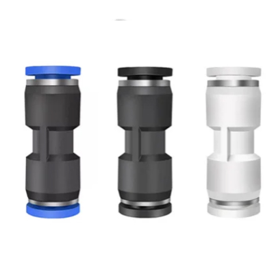
- Push-to-Connect Check Valves: This is the most popular choice for modern, fast-paced automation. A push-to-connect check valve (also known as a push-in check valve) allows users to instantly connect flexible pneumatic tubing (like PU, PE, or Nylon) without the need for tools or clamps. They are incredibly convenient for rapid assembly, maintenance, and tight spaces. **
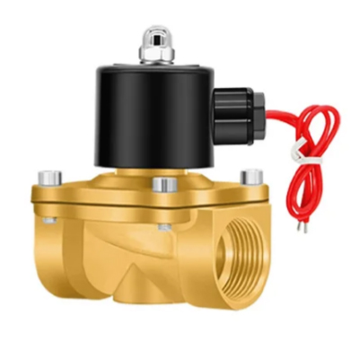
- Threaded Pneumatic Check Valves: For rigid piping, high-vibration environments, or direct installation into a cylinder port or compressor head, a threaded pneumatic check valve is required. These feature standardized male or female threads (such as NPT, BSPT, or G-thread) to ensure a secure, mechanical seal that won’t easily back out under stress. **
- Inline Air Check Valves: Both push-in and threaded styles are often designed as an inline air check valve. This means the valve is installed directly in the middle of a straight tubing run, saving space and keeping the air circuit clean and organized.
2. Material Selection: Brass vs. Stainless Steel
The environment where the valve operates is just as important as the pressure it handles. Choosing the wrong material can lead to premature corrosion and seal failure. When evaluating a brass vs stainless steel pneumatic check valve, consider the following:
- Brass (and Nickel-Plated Brass): This is the industry standard for general-purpose pneumatic applications. A brass pneumatic check valve offers excellent durability, good resistance to non-corrosive moisture, and is highly cost-effective. For added wear and mild corrosion resistance, nickel-plated brass is a superior upgrade.
- Stainless Steel: When your air lines are exposed to harsh chemicals, extreme temperatures, or frequent washdowns (such as in food processing or pharmaceutical manufacturing), a stainless steel air check valve (typically 304 or 316-grade) is mandatory. They provide the ultimate defense against rust and structural degradation.
- Composite/Plastic: Often used in conjunction with push-to-connect fittings, high-strength engineered plastics offer a lightweight and economical solution for standard, low-pressure automation tasks.
Sizing and Selection Guide: Choosing the Right Valve
Selecting the correct pneumatic check valve involves more than just picking a connection type. To ensure optimal performance and safety, you must match the valve’s technical specifications to your system’s exact requirements.
Here are the key factors to consider during the selection process:
- Port Size and Thread Standard: The valve must seamlessly integrate into your existing plumbing without causing unnecessary flow restrictions. Common sizes include metric push-in fittings (like a push-in non-return valve 8mm or 10mm) and imperial threaded ports (such as a 1/4″ NPT brass air check valve or 3/8″ BSPT). Always verify the thread standard of your mating components.
- Maximum Operating Pressure: This is a critical safety and performance metric. Standard automation systems operate between 0.5 to 1.0 MPa (70-150 psi). However, heavy-duty industrial applications demand much higher resilience. If your circuit experiences severe pressure spikes or operates under extreme loads, you must select a high pressure pneumatic check valve. Look for industrial-grade valves engineered to withstand working pressures up to 6MPa to guarantee safety and a zero leak seal under extreme stress.
- Flow Capacity (Cv Value): An undersized valve will create a bottleneck, starving your actuators of the air volume they need to operate at full speed. Always check the manufacturer’s flow rate specifications to ensure the valve can handle your system’s peak demand without inducing a severe pressure drop.
- Cracking Pressure: As discussed earlier, select a low cracking pressure check valve if your system is highly sensitive to energy loss or if you are working with very low-pressure control signals.
Quick Troubleshooting: Why is My Pneumatic Check Valve Failing?
Even the best components can experience issues due to poor air quality or improper installation. If you suspect backflow in your system, consult this quick troubleshooting guide:
| Symptom / Issue | Likely Cause | Recommended Solution |
|---|---|---|
| Continuous Leaking (Air passing in reverse) | Debris (teflon tape, rust) caught in the valve seat, preventing the seal from closing completely. | Remove the valve and flush it with clean air/solvent. Install a particulate filter upstream. |
| Severe Pressure Drop or Restricted Flow | The valve is undersized for the flow demand, or the internal mechanism is jammed with oil/sludge. | Verify the Cv rating. Replace the valve and ensure proper air lubrication levels. |
| Chattering or Buzzing Noise | The valve is installed too close to a reciprocating compressor, causing the internal spring to rapidly bounce with each pulse. | Relocate the valve further downstream or install a pulsation dampener (accumulator). |
Optimize Your Pneumatic System Today
Preventing backflow is not just about protecting your equipment; it’s about ensuring the long-term reliability and efficiency of your entire pneumatic operation. By selecting the right connection type, material, and pressure rating, you can eliminate unexpected downtime and costly repairs.
Ready to secure your air lines? Browse our extensive catalog of high-performance pneumatic check valves—ranging from quick push-to-connect models to heavy-duty 6MPa threaded brass solutions—or contact our technical team today to find the perfect fit for your specific application.
Frequently Asked Questions (FAQs)
Q: Can a pneumatic check valve be installed in any orientation? A: Generally, yes. Because most modern pneumatic check valves rely on an internal spring rather than gravity to close the seal, they can usually be installed vertically, horizontally, or at any angle. Always verify the flow direction arrow on the valve body during installation.
Q: What is the standard cracking pressure for an air line check valve? A: While it varies by design, most standard industrial pneumatic check valves have a cracking pressure between 0.01 MPa and 0.05 MPa (roughly 1.5 to 7.5 psi). Specialized low-pressure valves are available for highly sensitive applications.
Q: Do pneumatic check valves cause a pressure drop? A: Yes. Because the compressed air must continuously push against the internal spring to keep the valve open, a small pressure drop is inherent to the design. This should be factored into your overall system sizing calculations.