Introduction
Is your pneumatic impact wrench lacking torque? Does your cylinder movement feel sluggish, even though your compressor is running at full capacity?
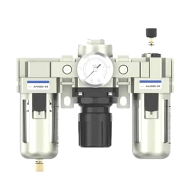
Before you blame the compressor or the tool itself, check your Air Preparation Unit (FRL).
One of the most common mistakes in pneumatic system design is undersizing the FRL unit. Many engineers and procurement managers fall into the “Port Size Trap”—simply matching the FRL port size to the existing pipe size (e.g., buying a 1/2″ FRL because the pipe is 1/2”).
Here is the hard truth: Physical port size does not equal flow capacity.
A standard 1/2″ FRL and a heavy-duty 1/2″ FRL might have the same threads, but their internal airflow characteristics (SCFM) can be drastically different. Choosing the wrong one can starve your tools of air, increase energy costs due to high pressure drop (Delta P), or—in the case of oversizing—prevent your lubricator from functioning correctly.
In this guide, we will look beyond the thread size. You will learn how to calculate the required Flow Rate (SCFM), understand the impact of Pressure Drop, and use Flow Characteristic Curves to select the perfect FRL unit for your specific application.
The Myth: Why Port Size Does Not Equal Flow Rate
Many people assume that a 1/2-inch NPT FRL will always deliver more air than a 3/8-inch NPT FRL. While this seems logical, it is often misleading.
The port size is merely the connection point, like a doorway. The true limitation to airflow is the internal flow path (orifice size) and the body design of the unit itself.
Imagine two FRL units:
- Unit A: A compact “Mini Series” FRL with 1/2″ ports.
- Unit B: A heavy-duty “Standard Series” FRL, also with 1/2″ ports.
Despite having identical connection threads, Unit B might have an internal flow path that is twice as large as Unit A. This means Unit B can deliver significantly higher SCFM (Standard Cubic Feet per Minute) with much less pressure drop.
Key Takeaway: Do not size your FRL based solely on your pipe diameter. A 1/2″ pipe might only need 20 SCFM, which a 1/4″ body size FRL (with 1/2″ adapters) could easily handle. Conversely, a high-speed application on a 1/2″ pipe might require the internal volume of a 3/4″ body size FRL to prevent starvation.
To choose correctly, you must look at the Flow Characteristic Curves provided by the manufacturer, not just the thread size stamped on the housing.
[Suggested Image: A side-by-side comparison of a Compact FRL and a Heavy-Duty FRL, both labeled “1/2 inch ports”, showing the difference in physical body size.]
Understanding Key Specs: SCFM, Pressure Drop, and Cv
To select the right FRL unit, you need to look beyond the port size and understand three critical metrics: SCFM, Pressure Drop (Delta P), and the Cv Factor.
1. SCFM (Standard Cubic Feet per Minute)
Think of SCFM as the “fuel” your pneumatic tools need to run. It measures the volume of air flowing through the system at a standard temperature and pressure.
- The Risk: If your FRL unit is rated for 20 SCFM but your impact wrench requires 30 SCFM, the tool will starve, resulting in low torque and slow operation.
2. Pressure Drop (Delta P)
Pressure drop is the difference between the air pressure entering the FRL (Inlet Pressure) and the pressure leaving it (Outlet Pressure). Every time air passes through a filter element or a regulator valve, it encounters resistance, causing pressure to drop.
- The “5 PSI Rule”: As a general rule of thumb for industrial applications, you should size your FRL unit so that the pressure drop does not exceed 5 PSI (0.35 bar) at your required flow rate.
- Why it matters: High pressure drop forces your compressor to work harder to maintain system pressure, wasting energy and increasing operating costs.
3. The Cv Factor (Flow Coefficient)
While SCFM can vary based on inlet pressure, the Cv value is a constant performance indicator of the FRL’s internal flow efficiency.
- Pro Tip: Use the Cv value to compare different FRL series objectively. A higher Cv means the unit can pass more air with less restriction (lower pressure drop).
Quick Reference: Air Consumption of Common Pneumatic Tools
Not sure exactly how much air your tools consume? Use this table as a starting point for your calculations.
Note: These values represent the continuous flow required while the tool is running at 90 PSI (6.2 bar). Always verify with your specific tool’s manual.
| Tool Type (Standard Duty) | Average Consumption (SCFM) | Recommended FRL Size (Body) |
|---|---|---|
| 1/2″ Impact Wrench | 25 – 30 SCFM | 1/2″ Standard Series |
| 3/8″ Air Drill | 15 – 20 SCFM | 1/4″ or 3/8″ Series |
| Die Grinder | 20 – 25 SCFM | 3/8″ or 1/2″ Series |
| Dual Action (DA) Sander | 10 – 15 SCFM | 1/4″ Series |
| Paint Spray Gun | 15 – 20 SCFM | 3/8″ Series (Requires High Flow) |
| 3/4″ Impact Wrench | 35 – 45 SCFM | 3/4″ Heavy Duty Series |
Step-by-Step Guide to Sizing Your FRL Unit
Once you have estimated your air demand, follow these four steps to select the perfect unit:
Step 1: Determine System Pressure
Identify your primary line pressure (usually 90-100 PSI). FRL flow rates are often rated at specific inlet pressures (e.g., 100 PSI). If your pressure is lower, the flow capacity will decrease.
Step 2: Calculate Total Flow Demand
Sum up the SCFM of all tools that will be operating simultaneously.
- Example: If you use a grinder (25 SCFM) and a blow gun (10 SCFM) at the same time, your FRL needs to handle at least 35 SCFM.
- Pro Tip: Add a 15-20% safety margin to account for pressure spikes and future expansion.
Step 3: Check the Flow Characteristic Curve
This is the most critical step. Do not just look at the port size! Look at the manufacturer’s Flow Chart. Find your required flow rate on the X-axis (e.g., 40 SCFM) and trace it up to the curve. Ensure that the Pressure Drop (Delta P) on the Y-axis is less than 5 PSI.
- If the curve shows a 10 PSI drop at your required flow, the unit is too small. Move up to the next body size.
Step 4: Select the Port Size
Now that you have confirmed the body size can handle the flow, choose the port size (NPT or G/BSP) that matches your piping to minimize the need for adapters.
Beyond Size: Features That Matter for Your Industry
Selecting the correct flow rate is only half the battle. To ensure your FRL unit survives in your specific environment, you must choose the right features.
1. Filtration Grade (ISO 8573-1 Standard)
- General Purpose: For standard pneumatic tools, a 40-micron filter (ISO Class 5) is sufficient to remove bulk water and large particles.
- Precision Applications: For paint spraying or sensitive instrumentation, you need a 5-micron filter followed by a 0.01-micron coalescing filter (ISO Class 1-2) to remove oil aerosols and fine dust.
2. Drain Type: Auto vs. Manual
- Manual Drain: Cost-effective but requires daily attention. If you forget to drain it, water will bypass the filter and damage your tools.
- Auto Drain: Highly recommended for FRLs installed in hard-to-reach locations. It automatically expels water when the bowl fills up, protecting your system 24/7.
3. Bowl Material
- Polycarbonate: Standard for most indoor applications. Warning: Incompatible with synthetic oils or solvent fumes.
- Metal Bowl: Essential for high-temperature environments, high-pressure systems, or areas with exposure to harsh chemicals.
The “Goldilocks” Rule: Common Sizing Mistakes
Mistake #1: Undersizing (The Energy Waster)
Choosing a unit that is too small causes a massive pressure drop. Your compressor works harder to push air through a restricted orifice, driving up energy bills and causing tools to feel “weak.”
Mistake #2: Oversizing (The Lubricator Trap)
“Bigger is better,” right? Not always. If you oversize your FRL unit significantly (e.g., using a 1-inch FRL for a tool that needs only 5 SCFM), the air velocity inside the unit will be too low.
- The Consequence: The Lubricator relies on air velocity to pick up oil drops. If the flow is too low (below the “Minimum Drip Flow”), the lubricator won’t work, and your tools will run dry.
- The Solution: Choose a size that handles your peak flow with a 15-20% safety margin—no more, no less.
Conclusion
Sizing an FRL unit isn’t just about matching the pipe threads. It’s about matching the Flow Rate (SCFM) to your tools’ demands while keeping Pressure Drop to a minimum.
By selecting the right body size, filtration grade, and drain type, you ensure your pneumatic system runs efficiently, prolonging the life of every tool downstream.
Ready to upgrade your air preparation system? Don’t guess. Download our complete [FRL Unit Catalog ] to find the exact match for your application. If you are still unsure about your flow requirements, [Contact Our Engineering Team] today for a free sizing consultation.