Selecting the correct Pneumatic Solenoid Valve is critical for the efficiency and safety of your automation system. Whether you are designing a new machine or replacing a failed component, making the wrong choice can lead to insufficient airflow, slow cylinder actuation, coil burnout, or even complete system failure.
With a vast array of options available—2/2 way, 3/2 way, 5/2 way, direct acting vs. pilot operated, and various voltage ratings like 24VDC or 110VAC—navigating the catalog can be overwhelming.
You might be asking:
- How do I calculate the required flow (Cv value)?
- Should I use a Normally Closed (NC) or Normally Open (NO) valve?
- Why isn’t my pilot-operated valve opening at low pressure?
In this comprehensive sizing guide, we will cut through the confusion. We’ll walk you through a step-by-step process to identify the perfect air directional control valve for your specific application, ensuring optimal performance and longevity.
By the end of this guide, you will understand:
- The difference between Direct Acting and Pilot Operated valves.
- How to choose the right Circuit Function (2/2, 3/2, 5/2 way).
- How to calculate the correct Cv Factor for your cylinder speed.
- Key electrical and environmental considerations (Voltage, IP65, Materials).
Step 1: Determine the Valve Function (Ways & Positions)
The first and most crucial step in selecting a pneumatic solenoid valve is determining its function. This is often described by two numbers, such as “3/2” or “5/2”.
- The first number represents the Number of Ports (Ways): How many connection points (Inlet, Outlet, Exhaust) are on the valve body?
- The second number represents the Number of Positions: How many switching states does the valve have? (Usually 2 or 3).
Here is a breakdown of the most common configurations and their applications:
2/2 Way Solenoid Valves (2 Ports, 2 Positions)
Best for: Simple On/Off Control (Air Blast, Shut-off)
A 2/2 way valve has one inlet (P) and one outlet (A). It acts like a basic light switch for compressed air.
- Application: Used for air nozzles, blow-off applications, or isolating a specific part of an air line.
- Configuration: Usually Normally Closed (NC) (air is blocked until energized).
3/2 Way Solenoid Valves (3 Ports, 2 Positions)
Best for: Single-Acting Cylinders
A 3/2 way pneumatic valve is designed to control a single-acting cylinder (cylinders with a spring return).
- How it works:
- Position 1: Air flows to the cylinder to extend it.
- Position 2: The supply is blocked, and the air inside the cylinder exhausts to the atmosphere, allowing the spring to retract the piston.
- Normally Closed (NC) vs. Normally Open (NO):
- NC: The valve is closed (cylinder retracted) when no power is applied. This is the most common safety choice.
- NO: The valve is open (cylinder extended) when no power is applied.
** Shop our collection of [ 3/2 Way Solenoid Valves].
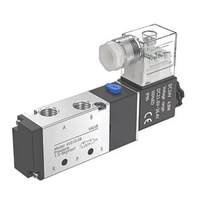
5/2 Way Solenoid Valves (5 Ports, 2 Positions)
Best for: Double-Acting Cylinders
This is the workhorse of industrial automation. A 5/2 way solenoid valve controls a double-acting cylinder, which uses compressed air to both extend and retract (no spring).
- How it works: One port is always pressurized while the other exhausts. Switching the valve reverses the airflow, changing the direction of the cylinder.
- Single vs. Double Coil:
- Single Solenoid: Uses a spring to return to the original position when power is lost (failsafe).
- Double Solenoid: Remembers the last position even after power is lost (bi-stable/memory).
5/3 Way Solenoid Valves (5 Ports, 3 Positions)
Best for: Stopping Cylinders Mid-Stroke
If you need to stop a cylinder in an intermediate position (not fully extended or retracted), you need a 5/3 way valve. These valves have a third “center” position when both coils are de-energized.
- Closed Center: All ports are blocked. The cylinder stops and holds its position (trapped air). Ideal for precise positioning.
- Exhaust Center: Pressure ports exhaust to the atmosphere. The cylinder stops but can be moved manually (floating). Ideal for safety setup allowing manual movement.
Step 2: Actuation Type – Direct Acting vs. Pilot Operated
This is the most common reason for solenoid valve failure or returns: selecting the wrong actuation type for the system’s pressure.
Just because a valve has the right port size doesn’t mean it will open. You must choose between Direct Acting and Pilot Operated based on your air pressure.
Direct Acting Solenoid Valves (Zero Differential)
Best for: Low Pressure, Vacuum, or Closed Loops
In a direct acting valve, the magnetic force of the solenoid coil directly pulls the plunger (armature) to open or close the orifice.
- Operating Pressure: 0 Bar to Max Pressure.
- Key Advantage: It does not require any pressure to operate. It will work even with 0 PSI or in a vacuum system.
- Trade-off: Because the coil has to do all the work, these valves usually have smaller orifices (lower flow) and consume more power to generate enough magnetic force.
Selection Tip: If you are controlling a gravity-fed system, a vacuum line, or a very low-pressure air supply (< 1 bar), you MUST use a Direct Acting valve.
Pilot Operated Solenoid Valves (Servo Assisted)
Best for: Standard Compressed Air Systems (High Flow)
Most industrial pneumatic valves (like the popular 5/2 way series) are pilot operated. They use the system’s own air pressure to help move the internal spool or diaphragm. The solenoid only controls a tiny “pilot” channel, and the air pressure does the heavy lifting.
- Operating Pressure: Typically 0.15 MPa (1.5 Bar) to 0.8 MPa (8 Bar).
- Key Advantage: High flow rate (High Cv) with very low power consumption.
- The Critical Requirement: They require a Minimum Differential Pressure (∆P) to function. If your air supply drops below ~1.5 Bar (22 PSI), the valve will not open or will chatter, even if the coil is energized.
⚠️ WARNING: Do NOT use a Pilot Operated valve if your system pressure is near zero. A common mistake is using a pilot valve for a vacuum application or simply “draining” a tank. Without the minimum back pressure, the internal spool will not shift, and the valve will appear “stuck.”
Step 3: Sizing the Valve (Flow Rate & Cv Calculation)
Many buyers make the mistake of selecting a valve based solely on the Port Size (e.g., “I need a 1/4 inch valve”). While port size is a good indicator, the true measure of a valve’s capacity is its Cv Value (Flow Coefficient).
What is Cv?
Cv represents the volume of air (in SCFM) that a valve can pass with a pressure drop of 1 PSI at 60°F.
- High Cv = High Flow: The cylinder moves faster.
- Low Cv = Low Flow: The cylinder moves slower or “starves” (jerky motion).
If you undersize the valve (Cv too low), your expensive pneumatic cylinder will crawl, hurting your machine’s cycle time. If you oversize it significantly, you waste money and panel space.
The “Rule of Thumb” Sizing Guide
For most general automation applications using standard pressure (0.5 – 0.7 MPa / 80 – 100 PSI), you don’t need complex calculus. You can estimate the required valve size based on your Cylinder Bore Size:
| Cylinder Bore Size (Ø) | Recommended Valve Port Size | Typical Cv Range | Application |
|---|---|---|---|
| 6mm – 16mm | M5 or 1/8″ | 0.2 – 0.5 | Grippers, small clamps |
| 20mm – 40mm | 1/8″ or 1/4″ | 0.5 – 1.0 | Light assembly, packaging |
| 50mm – 80mm | 1/4″ or 3/8″ | 1.0 – 2.5 | Heavy lifting, door openers |
| 100mm + | 1/2″ or larger | 3.0 + | Heavy industrial presses |
** Need exact calculations? Use our [Online Flow Calculator] or contact our engineering team.
Speed Matters
The chart above assumes “standard” speed (approx. 500mm/s).
- High Speed Applications: If you need the cylinder to extend instantly (e.g., sorting/ejection), jump up one valve size. (e.g., Use a 3/8″ valve for a Ø40mm cylinder).
- Flow Controls: Always install Speed Controllers (Flow Control Valves) on the exhaust ports of the solenoid valve. It is better to buy a valve with slightly more flow than you need and throttle it down, rather than having a valve that is too small.
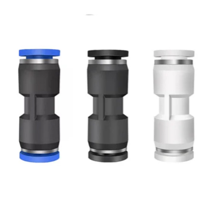
Pro Tip: Don’t forget the fittings! A valve with a Cv of 1.0 is useless if you choke it with a tiny 4mm tube fitting. Ensure your tubing and fittings match the flow capacity of the valve.
Step 4: Electrical Specifications (Voltage & Coil)
Once you’ve selected the valve function and flow, the final critical step is choosing the right Solenoid Coil and Electrical Connection. This is a 100% Go/No-Go decision—get the voltage wrong, and the valve either won’t work or will burn out instantly.
Voltage Selection: What’s the Standard?
- 24VDC (The Industry Standard):
- Pros: Safest (low voltage), global compatibility, most readily available, can be driven directly by PLC outputs.
- Cons: Requires a separate DC power supply.
- Recommendation: Unless you have a specific reason not to, always choose 24VDC for new machine designs.
- 110VAC / 220VAC:
- Pros: Can be wired directly to mains power (e.g., standard wall outlet). No need for a DC power supply.
- Cons: Higher shock hazard, coil generates more heat, electromagnetic noise (EMC) issues.
- Use Case: Legacy machines, simple standalone applications (e.g., a garage compressor drain).
- 12VDC:
- Use Case: Mobile equipment (trucks, agricultural machinery), solar-powered systems.
Coil Power Consumption & Heat
Solenoid coils generate heat—this is normal. However, modern Low Power Consumption coils (e.g., < 2.5 Watts) are highly recommended.
- Why Low Power?
- Cooler operation (extends coil life).
- Can be driven directly by sensitive PLC outputs without a relay.
- Energy savings for large valve manifolds (valve islands).
Connection Type & Protection
- DIN Connector (Form A/B/C): The most common standard. Allows you to unplug the cable without removing the coil. Look for LED Indicator Lights on the connector to easily troubleshoot if power is reaching the valve.
- Flying Leads (Wire Leads): Cheaper, but harder to replace.
- IP Rating:
- IP65: Dust-tight and protected against water jets. Essential for washdown environments or outdoor use.
⚠️ WARNING: Do NOT mix AC and DC coils! Putting 24VDC on a 220VAC coil will do nothing. Putting 220VAC on a 24VDC coil will result in immediate burnout and smoke.
Step 5: Material & Environment (Body & Seals)
The final piece of the puzzle is ensuring the valve can survive in your specific environment. A valve designed for a clean, dry server room will fail quickly in a hot, oily stamping plant.
Body Material: Aluminum vs. Brass vs. Stainless
- Aluminum Alloy (Standard for Pneumatics):
- Pros: Lightweight, cost-effective, excellent heat dissipation.
- Best For: 90% of general automation applications using clean compressed air.
- Brass:
- Pros: More durable, corrosion-resistant.
- Best For: Applications involving water, oil, or where the valve might be exposed to moisture.
- Stainless Steel (304/316):
- Pros: Ultimate corrosion resistance, food-grade safe.
- Best For: Food & Beverage, Pharmaceutical, or Chemical processing environments.
Seal Material: NBR vs. Viton (FKM)
- NBR (Nitrile Rubber): The industry standard. Good for oil resistance and temperatures from -5°C to +80°C. Choose this for standard air.
- Viton (FKM): High-performance. Resists harsh chemicals and high temperatures up to 150°C. Choose this if your factory is extremely hot or if aggressive oils are present in the air line.
Pro Tip: The NAMUR Interface If you are mounting a valve directly onto a pneumatic rotary actuator (for process valves like ball/butterfly valves), do not use a standard threaded valve. Look for a NAMUR Interface valve. These bolt directly onto the actuator without any external tubing, saving space and reducing leak points.
The Selection Cheat Sheet (Summary)
To make your life easier, use this quick reference table to find the right valve configuration for your application.
| Application / Load Type | Valve Function | Actuation Type | Notes |
|---|---|---|---|
| Air Blow / Nozzle / Shut-off | 2/2 Way (NC) | Direct Acting or Pilot | Simple On/Off control. |
| Single-Acting Cylinder (Spring Return) | 3/2 Way (NC) | Pilot Operated | Cylinder extends when on, retracts when off. |
| Double-Acting Cylinder (Push/Pull) | 5/2 Way | Pilot Operated | Most common industrial valve. |
| Cylinder Mid-Stop (Safety/Positioning) | 5/3 Way | Pilot Operated | Choose Closed Center to hold position. |
| Vacuum or Low Pressure (< 1 Bar) | Any | Direct Acting | CRITICAL: Pilot valves will not work here. |
| Rotary Actuator (Process Valve) | 5/2 Way (NAMUR) | Pilot Operated | Mounts directly to actuator (No tubing). |
Troubleshooting Common Issues
Even the best-engineered systems can encounter problems. Before you replace a valve, run through this quick troubleshooting checklist. It might save you time and money.
1. Valve Will Not Switch (Cylinder Won’t Move)
- Check the Pressure: Is your supply pressure above the minimum requirement? Remember, Pilot Operated valves need at least ~1.5 Bar (22 PSI) to shift. If you are testing on a bench with no air, the valve will click but not open.
- Check the Voltage: Measure the voltage at the coil terminals. A 24VDC coil needs at least 21-22V to pull in.
- Check the Manual Override: Most industrial valves have a small button or screw on the body. Press it. If the valve shifts manually but not electrically, the Solenoid Coil is likely burnt out or loose.
2. Air Leaking from the Exhaust Port
- Internal Seal Wear: If air constantly hisses from the exhaust port (R or S) while the valve is idle, the internal spool seals are likely worn or damaged by debris.
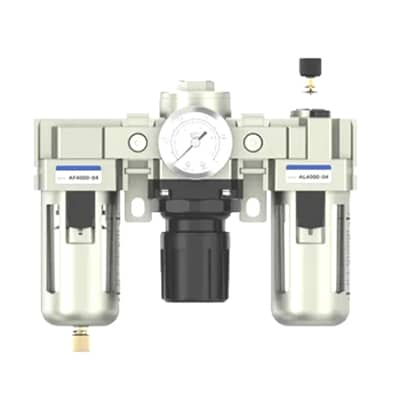
- Dirty Air: A single grain of sand or metal shaving can jam the spool slightly open. Always install a filter (FRL unit) before your valves to prevent this.
3. Solenoid Coil is Getting Extremely Hot
- Wrong Voltage: Did you plug a 24V coil into a 110V supply? It will overheat instantly.
- Incomplete Stroke: On AC coils, if the armature (plunger) does not fully seat inside the coil (due to debris blocking it), the current will spike, causing the coil to burn out within minutes.
Conclusion: The Perfect Fit for Your System
Selecting the right Pneumatic Solenoid Valve doesn’t have to be a guessing game. By following these 5 steps, you ensure your machine runs efficiently, safely, and without unexpected downtime.
Recap Checklist:
- Function: Do you need a 2/2, 3/2, or 5/2 way valve?
- Actuation: Is your pressure high enough for Pilot Operated, or do you need Direct Acting?
- Sizing (Cv): Does the valve flow enough air to move your cylinder at the required speed?
- Voltage: Is your power supply 24VDC, 110VAC, or 220VAC?
- Environment: Do you need IP65 protection or special seals for high temperatures?
Still not sure which valve is right for you? Our engineering team is here to help. [Contact Us] today for a free sizing consultation and get a recommendation within 24 hours.
FAQ (Frequently Asked Questions)
Q: What is the difference between a “Normally Closed” and “Normally Open” valve? A: A Normally Closed (NC) valve blocks airflow when it is not powered. When you turn the power on, it opens. A Normally Open (NO) valve allows air to flow when not powered, and closes when you turn the power on. For safety, most applications use NC valves.
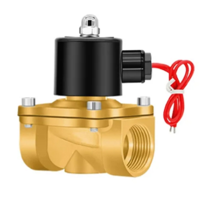
Q: Can I use a water solenoid valve for compressed air? A: Technically yes, but it is not recommended. Water valves are typically made of brass, are much heavier, slower, and more expensive than pneumatic aluminum valves. Pneumatic valves are specifically designed for the high-speed switching required in automation.
Q: How do I know if I need a 5/2 or 5/3 way valve? A: Use a 5/2 way valve if you just want the cylinder to go fully out and fully back. Use a 5/3 way valve if you need to stop the cylinder in the middle of its stroke (e.g., for safety or positioning).